Arduino UNO R3 – Technical Overview | Part 2
In Part 2, we continue the technical examination of the Arduino UNO R3 by covering its SPI interface, power pins, reset system, analog reference, I/O reference, USB interface, ATmega16U2, indicator LEDs, clock source, voltage regulation, DC power input, capacitors, ICSP headers, polyfuse and protection circuitry.
12. Arduino UNO R3 Board-Level Hardware
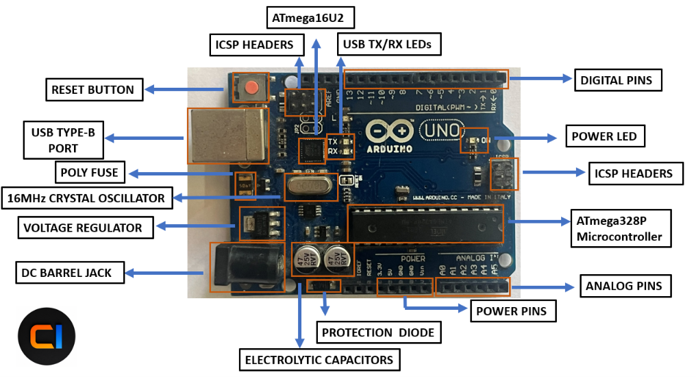
The Arduino UNO R3 is more than the ATmega328P microcontroller. The board integrates several supporting circuits that provide communication, power management, programming, clock generation, reset control and protection.
14. SPI Pins
The ATmega328P provides a hardware SPI (Serial Peripheral Interface) peripheral for synchronous serial communication.
| SPI Signal | Arduino UNO Pin | Function |
|---|---|---|
| MOSI | D11 | Master Out, Slave In — serial data transmitted from the controller to the peripheral |
| MISO | D12 | Master In, Slave Out — serial data transmitted from the peripheral to the controller |
| SCK | D13 | Serial clock generated by the SPI controller |
| SS | D10 | Slave Select / Chip Select signal |
SPI uses separate data-in, data-out and clock signals and is commonly used where relatively high-speed synchronous communication is required.
SD card modules, displays, sensors, memory devices, ADC/DAC devices and other SPI peripherals.
15. Power Pins
The UNO R3 provides several power-related pins through the power header. These pins allow the board to supply power to external circuits and accept an external supply through the appropriate input path.
| Pin | Technical function |
|---|---|
| 5V | Regulated 5 V supply rail available on the board for compatible external circuitry. |
| 3.3V | Approximately 3.3 V supply output generated by the board's 3.3 V regulator. Available current is limited. |
| GND | Electrical ground reference. Multiple GND pins are provided. |
| Vin | External input voltage path to the board's power circuitry when using an external supply. |
A common ground connection is required when interfacing external circuits with the Arduino so that both systems share the same electrical reference.
16. RESET Pin and Reset System
The RESET signal is used to reset the ATmega328P microcontroller.
When the RESET input is asserted LOW, the ATmega328P is reset. After reset is released, the microcontroller starts executing its program from the reset/startup sequence.
RESET Pin
External circuitry can reset the microcontroller by appropriately pulling the RESET line LOW.
RESET Button
The onboard push button provides a convenient way to trigger the reset circuitry.
17. AREF – Analog Reference
AREF stands for Analog Reference. The ATmega328P's ADC requires a reference voltage to determine the conversion range between the analog input voltage and the resulting digital value.
The AREF pin provides access to the ADC reference system when an appropriate reference configuration is used.
The ADC converts an analog input voltage into a digital number relative to its selected reference voltage. Therefore, the reference voltage directly affects the voltage range represented by the ADC result.
18. IOREF – I/O Reference
IOREF stands for I/O Reference.
On the Arduino UNO R3, IOREF indicates the logic operating voltage used by the board's microcontroller I/O system.
| Parameter | UNO R3 |
|---|---|
| IOREF level | Approximately 5 V |
| Purpose | Allows compatible shields to determine the board's I/O voltage level. |
This pin was introduced to improve compatibility with shields that may operate with different Arduino logic voltage levels.
19. USB Type-B Port
The USB Type-B connector provides the primary connection between the Arduino UNO R3 and a computer.
Program Upload
Compiled firmware can be transferred from the computer to the ATmega328P through the USB interface.
Serial Communication
The USB connection can also provide a computer-side interface for serial communication with the Arduino.
The USB signal does not directly connect to the ATmega328P's USB peripheral because the ATmega328P does not contain a native USB interface.
20. ATmega16U2 – USB Interface Microcontroller
The Arduino UNO R3 contains a second important microcontroller: the ATmega16U2.
Its primary role on the UNO R3 is to provide the USB interface between the computer and the ATmega328P's serial communication interface.
| Microcontroller | Primary role |
|---|---|
| ATmega328P | Main application microcontroller that executes the user's Arduino program. |
| ATmega16U2 | USB interface microcontroller used to bridge computer USB communication with the UNO's serial interface. |
During a typical USB programming process, the ATmega16U2 handles the USB side of the connection while the ATmega328P receives the serial data through its USART interface and uses the bootloader to process the upload.
21. USB Serial TX/RX LEDs
The USB interface section of the UNO R3 includes TX and RX indicator LEDs.
| LED | Indication |
|---|---|
| TX | Indicates transmit activity associated with the USB serial interface. |
| RX | Indicates receive activity associated with the USB serial interface. |
These LEDs provide a visual indication of serial activity. During operations such as sketch uploading, the LEDs may blink as communication occurs between the computer and board.
22. Power LED
The ON LED is the Arduino UNO R3's power indicator.
When the board receives suitable power, the power indicator LED illuminates.
23. 16 MHz Clock Source
The ATmega328P on the Arduino UNO R3 operates with a 16 MHz clock source.
The clock provides the timing reference required by the CPU and many hardware peripherals, including timers and communication interfaces.
CPU Timing
The clock provides the timing reference used by the AVR CPU to execute instructions.
Peripheral Timing
Timers, serial communication and other hardware functions depend on clock timing.
24. Voltage Regulator
The Arduino UNO R3 contains voltage regulation circuitry that helps generate the required regulated supply rails from appropriate external power sources.
The board can receive power through USB or through its external power input. When an external voltage is applied through the appropriate input path, the regulator circuitry helps provide the required operating voltage.
A linear regulator is not an unlimited power converter. Higher input voltage can result in greater power dissipation as heat.
25. DC Barrel Jack
The Arduino UNO R3 provides a DC barrel jack for an external DC power source.
This allows the board to operate without relying on the computer's USB connection for power.
| Power method | Purpose |
|---|---|
| USB | Power and computer communication through USB. |
| DC barrel jack | External DC power input. |
| Vin | External voltage input through the power header, depending on the chosen power configuration. |
26. Reset Button
The onboard RESET button provides a convenient way to trigger a reset of the ATmega328P.
When the button is pressed, the reset circuitry asserts the RESET line. Once reset is released, the microcontroller goes through its reset/startup sequence and the program begins execution again.
If a sketch is continuously blinking the onboard LED, pressing RESET causes the ATmega328P to restart its program execution sequence, so the sketch begins again.
27. Power Supply Capacitors
The Arduino UNO R3 board contains large SMD electrolytic capacitors in its power circuitry. In the board component documentation, capacitors such as PC1 and PC2 are used in the power section.
| Component | Value | Role |
|---|---|---|
| PC1 | 47 µF / 25 V | Power-supply filtering and transient energy buffering. |
| PC2 | 47 µF / 25 V | Power-supply filtering and stabilization. |
Capacitors store electrical energy and help reduce variations in the supply voltage. In power circuits, they can smooth transient changes and provide local energy during short-duration load variations.
ATmega328P Microcontroller
The ATmega328P is the main application microcontroller of the Arduino UNO R3.
The ATmega328P integrates the CPU, memory, GPIO, timers/counters, ADC, USART, SPI, TWI/I2C, PWM, analog comparator and other peripheral functions required for the main application.
28. ICSP Headers
ICSP stands for In-Circuit Serial Programming. The Arduino UNO R3 contains two ICSP headers because the board contains two AVR microcontrollers.
| ICSP Header | Associated device | Purpose |
|---|---|---|
| Main ICSP | ATmega328P | SPI-based programming and access to the ATmega328P. |
| USB ICSP | ATmega16U2 | Programming and firmware access for the USB interface microcontroller. |
The ICSP interface is particularly useful for low-level programming, bootloader programming, firmware development and advanced hardware applications.
29. Polyfuse – USB Overcurrent Protection
The Arduino UNO R3 includes a resettable polyfuse in the USB power path.
Its purpose is to help protect the USB supply path and board from excessive current.
Normal Operation
The polyfuse has relatively low resistance and allows the USB supply current to pass.
Excessive Current
When excessive current causes the device to heat, its resistance increases significantly and limits the current.
Unlike a conventional one-time fuse, a polyfuse is resettable. After the excessive-current condition is removed and the device cools, its resistance can return toward its normal operating condition.
30. Protection Diode
The Arduino UNO R3 uses diodes in its power circuitry to control current paths and provide protection against certain power-input conditions.
In the external power section, the protection circuitry helps prevent an incorrect power condition from directly damaging the board's power system.
A diode primarily allows current to flow preferentially in one direction. In a protection circuit, this property can be used to block or redirect unwanted current paths.
31. Practical Demonstration – Program Upload and D13
The different sections of the Arduino UNO R3 can be observed working together during a simple program-upload and LED test.
1. Computer
The computer communicates with the Arduino through the USB connection.
2. ATmega16U2
The ATmega16U2 provides the USB interface between the computer and the ATmega328P serial interface.
3. ATmega328P
The ATmega328P receives and executes the application firmware.
4. Flash Memory
The program firmware is stored in the ATmega328P's Flash memory.
5. 16 MHz Clock
The clock provides the timing reference required for CPU and peripheral operation.
6. Digital Pin 13
The ATmega328P controls the D13 output, which is connected to the onboard LED circuit.
void setup() {
    pinMode(LED_BUILTIN, OUTPUT);
}

void loop() {
  digitalWrite(LED_BUILTIN, HIGH);
  delay(1000);
  digitalWrite(LED_BUILTIN, LOW);
  delay(1000);
}
This simple example demonstrates how the computer, USB interface, ATmega328P, Flash memory, clock system, GPIO peripheral and onboard LED can participate in one complete operation.
32. How the Major Sections Work Together
| Section | Role in the UNO R3 |
|---|---|
| ATmega328P | Executes the application firmware and controls the main peripherals and I/O. |
| ATmega16U2 | Provides the USB interface to the computer. |
| Flash | Stores program firmware. |
| SRAM | Stores temporary runtime data. |
| EEPROM | Stores non-volatile application data. |
| 16 MHz Clock | Provides the timing reference for the microcontroller system. |
| SPI | Provides synchronous serial communication. |
| USB | Provides computer connectivity and programming communication. |
| Voltage Regulator | Generates regulated supply rails from suitable power inputs. |
| Polyfuse | Provides resettable overcurrent protection in the USB power path. |
| Capacitors | Filter and stabilize power-supply voltage. |
| RESET | Restarts the microcontroller through the reset/startup sequence. |
Part 2 – Technical Summary
Arduino UNO R3 – Complete Technical Picture
The Arduino UNO R3 is not simply a microcontroller mounted on a board. It is a complete development platform combining the ATmega328P application microcontroller with USB communication, power regulation, clock generation, reset circuitry, programming interfaces, protection components and multiple external interfaces.
The ATmega328P provides the processing core, memory, GPIO, ADC, timers, PWM, USART, SPI and TWI/I2C peripherals. The ATmega16U2 provides the USB interface required for convenient computer connectivity and programming.
Once these sections are understood, the Arduino UNO R3 can be viewed as a complete embedded system rather than simply a development board. 🚀